 |
Corner and Gate Post Assembly using 8" Irrigation
Mainline and 2.5" round tubing |
 |
Latch Post Assembly and single posts with flanges to
hang 2X6 panels. All are Concrete filled. |
About six years ago we dug up about 600' of old 8" steel irrigation mainline. Over time, it had rusted to the point of being unusable. As really good fence posts became harder to get and the price of even lower quality posts continued to rise, I decided to use the old mainline for corners, gate posts, intermediate braces, and other places where we needed strength and permanence. I built the assemblies at the shop and we hauled them out, dug holes, set them in, and (since the irrigation tubing is thin walled and not able to serve as a post by itself) filled the whole setup with concrete.
Six hundred feet of tubing doesn't go as far as you might think. We made corners and braces and fancy setups with wood panels between and we made water gap braces.
Finally, we ran out of the mainline. I priced thin walled tubing and I looked at the secondary steel yard in our area. The best price I could get on new tubing would have made a seven foot post blank cost about $45.00. The secondary yard didn't have much quantity but the price of secondary steel has gone up so much that each post blank would have cost about $30.00.
Concrete fence posts are not a new idea. Many areas around the U.S. and elsewhere have used concrete posts in areas where wood is not available or where wood will rot out about as fast as you put it in the ground. Most concrete posts, however, are manufactured in forms lying horizontally, cured, and then installed about like a really heavy wood post. The idea I had is to take the forms to where the posts are needed and pour them in place. I decided to build three forms. Two identical line forms and one corner form. The corner form later morphed into a three way form.
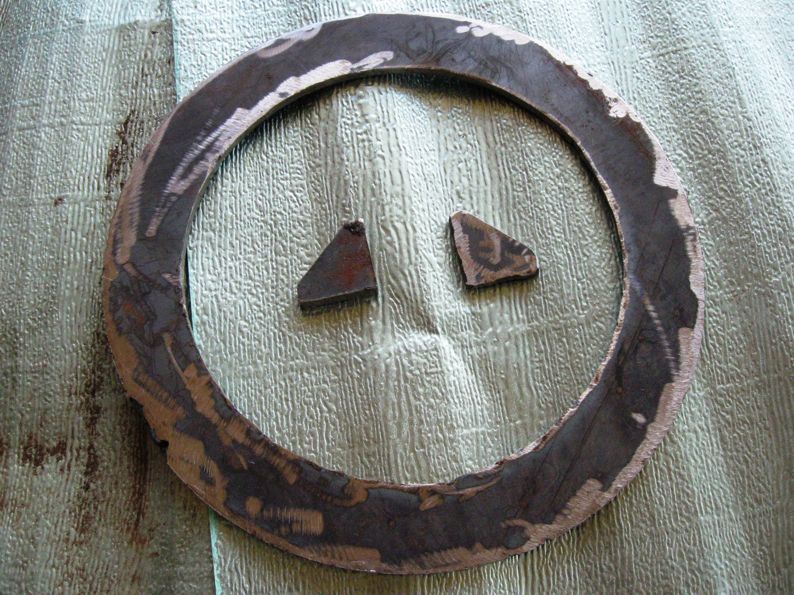
 |
| Tube with cutouts for sockets |
 |
The Raw Materials: 8" x 82" x 1/4" steel
tubing, 3" id steel tubing, 1/4" and 3/8"
steel plate, and 5/16" x 1" flat steel |
I found enough materials at our local secondary steel yard to do the job. They cut the 8" material to length for me so I wouldn't have to go home and get my trailer. Everything is secondary except the 5/16 by 1" flat strip. The cost was $468.00.
The fabrication is straight forward. I used 3" id x 1/8" tubing for the sockets because I have a truck load of 21/2" tubing to use as rails. The Stiffener Rings are 3/8" plate on the tops and bottoms, and 1/4" plate for the intermediates. The gussets match the rings with four each on the tops and bottoms and eight each on the intermediates. The flanges are from 5/16" x 1" flat steel. They were simply custom cut in pairs for each location and drilled to accept a 3/8" bolt. Each pair has at least one bolt hole to hold the pair together as it was welded in place.
 |
| Ring Stiffener Blanks |
 |
| Ring Stiffener and Gussets |
I
In an attempt to get the sockets more or less parallel between the line posts and the corner post, I set up the tubes with the socket holes cut out and the socket blanks roughly in place. Two of the intermediate ring stiffeners were also put in place on each post between the appropriate sockets since they can't be easily added after the sockets are welded in place. After worrying and fretting long enough to have done the job, I
 |
| Three Post Setup to get sockets placed correctly |
 |
| Sockets |
 |
| Gusset layout from drop |
 |
| Adding Ring Stiffeners and Gussets |
finally decided that perfection isn't necessary here. The results aren't elegant but there is enough room between the 3" socket and the 2 1/2" rail to compensate for some small misalignment problems.
 |
| Flanges |
I also spent time making certain everything was plumb and level before tacking the sockets in place. That was probably mostly wasted time. Certainly, you don't want to just throw things together, but obsessing over a tube being a quarter inch out of plumb isn't necessary here.
 |
| Sockets tacked in place and Stiffeners loosely set |
After the sockets are tacked in place, I laid each unit on a work table and tacked on the Ring Stiffeners and the Gussets. From the start, I knew there would be some warp in the finished form pieces but I still tried to weld everything up in stages so the warp wouldn't be excessive. When I finished this phase, the ring stiffeners, gussets and sockets were welded solid except near where the parting cut and flanges would go.
 |
Plasma-cut line (This process was later changed to cut
only between each set of stiffeners at one time.) |
 |
| The first form cracked open. We wanted a little warp |
On the first form, I used the plasma cutter to make the cut line through the tubing, the rings, and the sockets as I went along. After the first half of the first form it seemed easier and more accurate to snap a line, corresponding to the line through the sockets, across the stiffeners (since they stick up higher than everything else) and then cut them down to the tubing with a zip wheel. I used those cuts to hold the snap line while I marked the sockets and I also cut them down to the tubing with the zip wheel. Then it was easy to plasma cut the tubing between the various places and to finish the cuts through the tubing below the rings and sockets. (The socket blanks stick through the tubing on the inside as much as half an inch and the plasma cutter can be used inside the socket itself to cut the line.)
I custom cut all of the flange pairs before I started each cut along the length of the tubing. With the flange pairs cut and drilled and bolted together it was just busy work to plasma cut the cut line, clean up the little bit of slag and weld the flanges in place. The flanges are not welded solid on the outside because I thought the possibility of too much warp wasn't worth the small benefit.
When I finally cracked open the first form and it fell apart easily, I tried to forget about those times when I have welded things together that were supposed to be apart. It's worth mentioning though, that if you don't get a clean cut line you may have an interesting time getting the parts apart. It's also worth noting that you need to look closely to be certain you have removed all of the bolts before you try to crack the form open.
 |
| Finished inside on left, raw inside on right |
Once the form is open, it takes awhile to clean up and weld up the inside and then grind everything smooth. I did weld solid the flange on the inside. After both parts are finished, I gave the entire inside a thorough going over with a stiff wire wheel and then coated the interior with form release, diesel in our case.
The corner post began as simply a corner post
 |
The Corner Post has three columns of Sockets so it
can be used as a corner, a T, or a three-in-a-line brace. |
with sockets 90 degrees apart. When I finally realized that the form would still have to be three pieces I decided to add another set of sockets and make two quarters and one half piece. The versatility is greatly increased and the labor was minimal.
 |
| Two nearly finished forms |
 |
| The Corner Post has one half-Section and two Quarter-Sections |
 |
| We wanted some warp but maybe not quite this much |
The warp problem reared its head, or maybe its curve, on the quarter sections of the corner post. It takes a 3" bolt to get the parts started together. With the large number of bolts available, though, the whole thing goes back together easily.
 |
Even with the excess warp, the quarter-sections are
easy to put together with all of the available bolts. If you
expand this photo you can see the index notches
between the sockets on the right. The not visible side
flange has a single notch index in the same location. |
These forms are heavy. The line forms weigh about 170 lb. and the corner form weighs about 185 lb. Also, with each of these forms being custom made, I welded a "1" on the two pieces of a line post form and a "2" on the two pieces of the second line post form. The corner post form got a "3" on each of its pieces plus it got index marks (notches with the zip wheel) so the two quarter sections can be indexed to the proper position
JCE


No comments:
Post a Comment